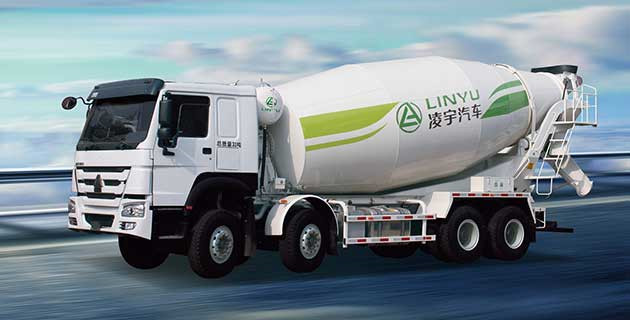
The mixing truck is composed of a vehicle chassis and a special device for concrete mixer trucks. The chassis of mixer trucks on the market mostly adopts the second-class general chassis provided by the vehicle manufacturers. Its special mechanism mainly includes the structure of the mixing drum, the loading frame, the feeding, discharging, operation and hydraulic systems. The power of the chassis of the car is taken out through a power take-off device, and the variable pump of the hydraulic system is driven, and the mechanical energy is converted into hydraulic energy to be transmitted to a fixed amount of motor. Let's take a closer look at the structure of the mixer truck and the corresponding maintenance measures.

The mixing tube is the core of the entire upper part.It has high technical content, small tolerance range, high precision requirements, and residual performance.It also directly affects the quality of the premixed mixer.If the design is not properly manufactured, the blade is double-log The spiral line is the theoretical basis. After actual testing and simulation correction, the current blades with fast feeding and discharging performance, low residual rate and ensuring the quality of ready-mixed concrete are formed. The stirring blade can prevent and help improve the discharge performance of the concrete. There are holes in the blade at the front of the outlet, which can reduce the adhesion of the concrete to the blade and improve the uniformity of the discharge. The sliding angle of the bottom of the mixing cylinder is continuously increased to ensure that the blades fully stir the concrete and reduce the residual rate.The production of the mixing cylinder is made of integrated external card and internal support. The requirement of the coaxiality of the reducer axis and the raceway axis is guaranteed. Make the whole vehicle run smoothly and comfortably, and the load impact force is small. The material of the mixing tube is a wear-resistant high-strength steel plate. After the shape of the mixing tube is formed, the inner support is removed and the blades are welded. The blade material is made of high wear-resistant 16Mn steel material, the wear resistance of the blade is increased by 15%, the double logarithmic variable pitch design, the mixing quality and the discharge speed are perfectly balanced. The welding process uses carbon oxide shielded welding. After the mixing cylinder is manufactured, it is shot peened to eliminate the stress generated during welding and manufacturing, and also increase the adhesion of the paint. After the final pre-installation of the upper body part, the whole process of shot blasting, rust removal, sanding, painting and baking is performed.
The frame system is divided into front seat, rear seat and auxiliary frame. The beam type of the upper sub-frame is front and rear through-holes. It adopts a fully-enclosed rectangular tube structure or a steel plate pressed into a groove shape. All materials are made of 16Mn steel. The chassis has the advantages of high strength, small deformation, and good stability.
The maximum size of the most hopper is 1075 × 1075, the single side is flat, and the remaining three sides are curved funnel shapes. It is locally strengthened in places where it is easy to wear. Because of its large internal space, it is easy to remove the residue at the inlet of the mixing drum, and its design angle is reasonable, so that the feeding speed is accelerated, and the phenomenon of blocking and jamming is not easy to occur.
The discharge chute can rotate 180 ° in the horizontal direction, and there is a limit device every 20 °. The compression spring type is used in the vertical direction, which can be lifted and lowered freely, so as to meet the requirements of different working conditions. The whole chute is divided into two parts, the main chute and the auxiliary chute. The most susceptible parts on the main chute are locally strengthened. The optimized design of the discharge chute is conducive to improving the flow performance of the concrete and the discharge speed. The discharging chute is provided with a locking device, which is fixed and locked during the running of the vehicle to ensure safe and reliable driving.
The operating system adopts a rod control system with accurate positioning and reliable control. The control points are divided into three parts: the cab and the two sides of the rear of the car. The operating lever in the cab can also control the steering of the mixer drum to ensure that the mixer drum is in an agitated state during vehicle driving. The entire control system has a compact structure, flexible operation and reliable control.
The hydraulic driving method uses a manual servo variable axial piston pump, a fixed piston motor and a reducer to form a closed hydraulic transmission system, which can be stepless forward and reverse speed change, and it is easy to adjust and control. The large-capacity oil tank set in the hydraulic circuit not only plays a role of storing oil but also radiating heat, so as to ensure normal work at an ambient temperature of -20-50 °. The reducer is directly connected to the bottom of the mixer.The output shaft connected to the reducer can be deflected within ± 6 °, which can compensate the displacement of the axis of the mixer, and ensure that the drive of the mixer is not distorted during the driving process of the car. Impact.
The water supply system adopts gas-type water supply. The compressed gas passes from the main tank of the main vehicle through a single-circuit protection valve, air source switch, pressure reducing valve, and one-way valve to the pressure water tank. The water in the water tank is pressed into the water pipe. The pressure reducing valve can be adjusted freely in the range of 00.3Mpa. The water tank has a capacity of 350 liters and is equipped with a hose and a flushing device for easy flushing.

The proper use and maintenance of the mixer truck directly affects the life of the vehicle and the rate of mechanical integrity. How to maintain and maintain the several assembly systems of the mixer truck.
When the engine reaches the maximum speed, the speed of the mixing drum should not exceed 15 revolutions per minute, otherwise, the wall of the mixing drum and the stirring blades will wear prematurely after being filled with materials; during the operation, the operating system is used to adjust the speed of the mixing drum. When waiting for unloading, the rotation speed of the mixing drum must be adjusted to not less than 10 revolutions per minute, otherwise the quality of the mixture will be affected; there is a round nut on the roller supporting the mixing drum to set and adjust the bearing clearance. The spiral blades in the mixing drum are severely worn. They should be inspected once a year and preventive repairs should be performed every two years.
There should be no leakage of slurry between the concrete inlet and the mixing drum. Generally, the gap between the inlet and the mixing drum is not more than 5mm. If the slurry leaks, it should be repaired according to different models, some of which are replaced with wide rubber bands and some are welded with thin steel plates, the size is larger than a half circle.
The working pressure of the hydraulic pump and hydraulic motor of the mixing drum is 40 ~ 45Mpa. The pressure of the hydraulic system should conform to the requirements in the operating instructions of the hydraulic parts. It should not be adjusted at will. The oil quality and quantity of hydraulic oil should meet the original requirements.
During the oil change, the first oil change time is performed after 500 hours of pick-up work, and the second and subsequent oil change intervals should be about one year; it is worth noting: each oil change must be run only when the operating temperature is reached. After replacement, the sealing performance of the entire system must be checked after each oil change, and all bolts, drain plugs and hose connections must be re-tightened. It should also be noted here that when removing any part of the hydraulic system, the interface should be sealed immediately. To prevent dust from entering.
When there is danger of icing during winter operation, the water supply system components must be drained, as long as all the control valves are opened to drain the water, and they are tightened one by one when refilling the water. Before the vehicle runs, close the intake control valve of the water supply system to avoid affecting the braking performance of the vehicle.
The above is all about the mixer truck. Only by knowing the structure and maintenance of the mixer truck in detail can you drive safely and extend its service life to a certain extent.
How to properly operate a concrete mixer truck
What are the reasons for the slippage of the oil tank truck clutch?
Was the heavy truck market lackluster in January? Will the market get off to a strong start to the year?
2026-02-10 10:17Momentum Set for 2026! CIMC Vehicles' DTB & Concrete Mixer Truck Business Group Achieves a Strong Start
2026-02-10 10:05Cement mixer truck antifreeze guide: A more effective method than wearing a down jacket
2026-02-10 09:53Another repeat purchase! Jinan's leading enterprise once again chooses CIMC Vehicles' new energy mixer trucks.
2026-01-15 15:59Address:Zhangheng Street corner Guanlin Road, Science and Technology Park, Luolong District, Luoyang City, Henan Province
E-mail:shiyk@lingyu.com
Phone:0086-379-65937678